Turbulent flat plate
Overview
- Solver: simpleFoam
- 2D flat plate test case based on the reference https://turbmodels.larc.nasa.gov/flatplate.html
- Zero pressure gradient
- Reynolds number based on the plate length of
- Turbulence is modelled using the kOmegaSST
- turbulentFlatPlate
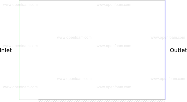
The domain comprises a 2D rectangular slab as shown below:
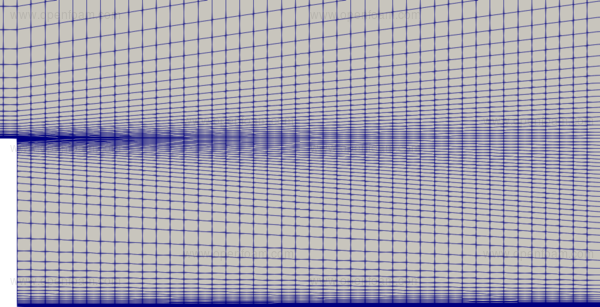
Mesh
Several meshes are employed to highlight the sensitivity of the computed skin friction coefficient to the near wall over the range . All meshes are generated using blockMesh and employ the same number of cells whereby the first cell height is varied by changing the expansion ratio from the wall patch.

Boundary conditions
Common fields
Velocity: U
| Patch | Condition | Value |
|---|---|---|
| Inlet | fixedValue | 69.4 m/s in x |
| Outlet | zeroGradient | |
| Walls | noSlip |
Pressure: p
| Patch | Condition | Value |
|---|---|---|
| Inlet | zeroGradient | |
| Outlet | fixedValue | 0 Pa (static) |
| Walls | zeroGradient |
Turbulence viscosity: nut
| Patch | Condition | Value |
|---|---|---|
| Inlet | calculated | |
| Outlet | calculated | |
| Walls | nutUSpaldingWallFunction |
Turbulence fields
Inlet conditions are based on an inlet turbulence intensity of 0.0039%, and turbulence viscosity ratio of 0.009.
Turbulence kinetic energy: k
| Patch | Condition | Value |
|---|---|---|
| Inlet | fixedValue | based on 0.039% intensity |
| Outlet | zeroGradient | |
| Walls | kqRWallFunction |
Turbulence specific dissipation rate: omega
| Patch | Condition | Value |
|---|---|---|
| Inlet | fixedValue | based on nut/nu = 0.009 |
| Outlet | zeroGradient | |
| Walls | omegaWallFunction |
Results
The following figures show the predicted skin friction coefficient as a function of Reynolds number, compared against the experimental data from Weighardt 88

